Roy's Ecotec Manx I build completion
- joescoolcustoms
- Posts: 286
- Joined: Mon Jun 03, 2013 5:00 am
- Location: Saint Albans, WV
Roy's Ecotec Manx I build completion
Roy had spoken to me at the Manx Club's 2014 Big Bear event about completing his Ecotec Manx. Well, his position in line has come, and the work is progressing nicely.
This is not a basic build, but a highly modified and tricked out build and I am proud to be a part of it. Roy has already had a significant amount of work done before bringing it to me for completion. Turn Key Manx shortened the chassis, installed a 3 inch body lift and got it as a full roller. Roy flat tow'd (no pun intended) it from SoCal to Richmond VA in August '14. In January '16 Roy brought it to me with a truck bed full of parts.
This is going to be a very cool project!
6 Rib Type II trans built by Rancho, converted with a Berg gear carrier mid section to a type I nose cone to keep the shift rod in the tunnel. This picture also shows how the chassis was "stretched" 3 inches so the Ecotec engine had enough room and not be shoved into the rear package trey.
Porsche 911 seats, fully reclining.
Saco Hydraulic Clutch located in the tunnel.
I have already made significant progress in the build, and have taken a lot of pictures so far. As time, rest periods and boredom happen, I will update this thread on kind of a task driven subject.
Re: Roy's Ecotec Manx I build completion
Can't wait to see this one as it goes on! And I have to again give him a huge thank you for letting my paint take his spot last year.
(Loretta) Manx # M2940D910E on customized 1970 chassis that has been "Wheelerized" by Joescoolcustoms
(Scarlett) Manx Resorter #12 (R0012B931S) on 1969 chassis.
(Gunther) Manx 2 # A0202A035E
Tow'dster # TF530G913S
Original Home built buggy that I learned to drive in back in 1995 (the one that started my passion).
Club Member # 4436
Loretta: http://www.manxclub.com/forum/viewtopic ... t=3365Manx" onclick="window.open(this.href);return false;
- joescoolcustoms
- Posts: 286
- Joined: Mon Jun 03, 2013 5:00 am
- Location: Saint Albans, WV
Re: Roy's Ecotec Manx I build completion
I am enjoying it so far. A lot of new-to-me things I get to be exposed to and figure out for Roy.
First up was to make the Aluminum fuel tank fit. This is one of the first few TKM made about 3 years ago, and then stopped. I cannot remember the capacity, but it fills the void under the hood and extends over the front firewall.
I had to "round" the corners of the fuel tank opening in the body slightly so it would fit down into the body. Also, since it is grabbing all the space available, the wooden lift block had to be removed for it to fit.
Sweet set up for sure! The bottom is double tapped for fuel supply and fuel return. Ecotec is fuel injected and requires feed and return.
Kind of hard to see, but the tank fills the void and the low profile filler cap is right against the bottom of the hood.
More to come.
- joescoolcustoms
- Posts: 286
- Joined: Mon Jun 03, 2013 5:00 am
- Location: Saint Albans, WV
Re: Roy's Ecotec Manx I build completion
The next step is to get the body mounted to the chassis so that other things can be fabricated and locations established.
I made two threshold plates to sandwich the body between. This gives a good flex free foundation. The steel is 1 1/2 inches wide and 1/4 inch thick. I slot cut the curve area, bent to the shape of the body, than welded the cuts solid, ground the welds smooth.
Next, 1/8 inch holes were drilled in the plate as pilot holes for the body to chassis bolts. This allows the use of the small bit to drill through the body and the top of the chassis rail. I then stick a rivet upside down in the drilled holes to help keep alignment as the rest of the holes are drilled.
Once all the pilot holes are drilled, the plate are put back onto the drill press and the holes drilled to final size, and the holes in the body and chassis drilled to size.
Since a lot of the fabrication is done before any paint, the fabrication needs to be accurate. If the body is direct bolted to the chassis, and then holes and so forth drilled into the glass, they need to be dead on. If a seal is used between the body and chassis, it may change the height of the body and the holes will be slightly off. So, I wanted to get the body at it's finished location before continuing with fabrication.
Original pan gaskets will be used to seal this body to the chassis and they do add a touch of height. The gasket was cut a bit long, holes marked and punched for the bolts.
Each gasket was labeled so to get the custom fit when it goes together for the final time.
As can be seen, small stainless steel screws were used on each gasket to keep them in place. If you have ever tried to put body gaskets on, they tend to flop all over and a real pain to get fitting exact during the final assembly.
And the body is bolted down solid.
- joescoolcustoms
- Posts: 286
- Joined: Mon Jun 03, 2013 5:00 am
- Location: Saint Albans, WV
Re: Roy's Ecotec Manx I build completion
Since seat location is very important for other fabrication aspects, they need to be mounted early on so as to be sure where the rest of the items end up.
The seats being used are 911 Porsche. Very nice, but a touch too wide to sit down into the floor area. But since the body has a 3 inch left, this is not a overheight problem, and they actually end up in a good position for leverage on the pedals. The original slider tracks for the 911 seats were modified to be as low as possible.
A simple seat mount was welded in, and the original VW style seat tracks removed.
The seat tracks were set on the new 2 inch wide X 1/4 thick mounts and the appropriate holes marked, drilled and deburred. Since the mounts are welded direct to the chassis, they are super strong and do not flex.
This position allows for the seat to be pushed as far towards the rear as the body will allow.
And since I set them up with the sliders all the way back, in the back position, they slide really far forward for shorter drivers.
At 6'2", I can get very comfortable in them with respect to the shifter and pedals. Another cool side effect of mounts installed this way is the large storage area under each seat. Anyone who travels long distances in their buggy to and from Manx Club events, this is a super valued resource.
Re: Roy's Ecotec Manx I build completion
Typical awesome work from Joe!
- joescoolcustoms
- Posts: 286
- Joined: Mon Jun 03, 2013 5:00 am
- Location: Saint Albans, WV
Re: Roy's Ecotec Manx I build completion
Thanks Ben! Because almost anything you do to a buggy is not wrong, they are super fun car to work on and modify. I try to describe my builds in simple detail to maybe encourage others to work on theirs.
So, since at the time of the Chassis work was being done, Roy had not completely decided on how the transaxle was going to be installed, the shift rod was not completed. I pulled the shifter off and the shift rod out of the tunnel after measuring it for the adjuster. (I forgot to photo how to measure the length of a shift rod for shortening with an adjuster. But I will try to describe it)
Once cut to the length needed, I drill opposite side of the rod right near the end and rosette weld the female adjuster end onto the rod. Be careful here, too much heat and the penetration will foul the inside threads.
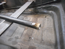
The weld has to be ground back to the original diameter of the rod so it will slide into the front shift rod hanger/bushing.
So, how do you measure for shortening a shift rod? This is not the end all, only way it can be done, your wrong if you do it another way style. It is a way I figured out how to do it that is decently simple and has not failed me yet. This is for shortening and using the weld on adjuster.
First, if you have a full length rod, I shorten it close, but still too long. Just enough that it can be re-installed and be able to center the front "cup" in the shifter hole and be just a little longer than the the edge of the hockey stick on the nose cone of the trans.
Next, I install the adjuster onto the shift rod-to-hockey stick coupler, and onto the hockey stick. The adjuster has two adjustments. One of for radial adjustment, (twist) and the other is for length. I spin the weld end onto the threaded portion of the adjuster and run it all the way rearward. I make a mark on the threads with a sharpie marker. Then I spin the weld end back off until only half of the threads on the weld end are still on the threaded portion, and mark it again.
What this does is show me the area that is adjustable. Some threads have to stay in the weld end to be stable and attached. So, I then mark the center between those two marks and that is my reference point. Spin the weld end up to that reference mark.
Next, the shift rod is centered in the shift rod hole with the cup facing up so you can see it is evenly in the hole. I put the hockey stick on the nose cone of the transaxle in neutral. So, both the shift rod is in neutral position and the trans hockey stick is in neutral position. I then move the shift rod right beside the adjuster, and mark were it needs to be cut in reference to where the weld end is on the threaded portion of the adjuster. Pull it back out, cut straight across, drill and weld it.
Paint it so it does not rust. Polish the front end right behind the cup so it is smooth for the nylon bushing, grease it and install it.
Clear as mud?
So, since at the time of the Chassis work was being done, Roy had not completely decided on how the transaxle was going to be installed, the shift rod was not completed. I pulled the shifter off and the shift rod out of the tunnel after measuring it for the adjuster. (I forgot to photo how to measure the length of a shift rod for shortening with an adjuster. But I will try to describe it)
Once cut to the length needed, I drill opposite side of the rod right near the end and rosette weld the female adjuster end onto the rod. Be careful here, too much heat and the penetration will foul the inside threads.
The weld has to be ground back to the original diameter of the rod so it will slide into the front shift rod hanger/bushing.
So, how do you measure for shortening a shift rod? This is not the end all, only way it can be done, your wrong if you do it another way style. It is a way I figured out how to do it that is decently simple and has not failed me yet. This is for shortening and using the weld on adjuster.
First, if you have a full length rod, I shorten it close, but still too long. Just enough that it can be re-installed and be able to center the front "cup" in the shifter hole and be just a little longer than the the edge of the hockey stick on the nose cone of the trans.
Next, I install the adjuster onto the shift rod-to-hockey stick coupler, and onto the hockey stick. The adjuster has two adjustments. One of for radial adjustment, (twist) and the other is for length. I spin the weld end onto the threaded portion of the adjuster and run it all the way rearward. I make a mark on the threads with a sharpie marker. Then I spin the weld end back off until only half of the threads on the weld end are still on the threaded portion, and mark it again.
What this does is show me the area that is adjustable. Some threads have to stay in the weld end to be stable and attached. So, I then mark the center between those two marks and that is my reference point. Spin the weld end up to that reference mark.
Next, the shift rod is centered in the shift rod hole with the cup facing up so you can see it is evenly in the hole. I put the hockey stick on the nose cone of the transaxle in neutral. So, both the shift rod is in neutral position and the trans hockey stick is in neutral position. I then move the shift rod right beside the adjuster, and mark were it needs to be cut in reference to where the weld end is on the threaded portion of the adjuster. Pull it back out, cut straight across, drill and weld it.
Paint it so it does not rust. Polish the front end right behind the cup so it is smooth for the nylon bushing, grease it and install it.
Clear as mud?
Re: Roy's Ecotec Manx I build completion
Now you've got me thinking, Joe... Been doing a bunch of reading on Ecotec swaps and it doesn't sound all that complicated with the right adapter. About 25 pounds heavier than a 1600, lots of bolt-ons available, plenty of them out there, and there's so much out there of people documenting their swaps (in Bajas and rail buggies, anyhow). What I really like about the Ecotecs is their proven reliability. Granted, one would lose some of the charm from an aircooled VW engine, but the thought of 160 horsepower out of a stock $400 engine sure has a nice ring to it! What radiator are you planning on using and where are you planning on mounting it?
- joescoolcustoms
- Posts: 286
- Joined: Mon Jun 03, 2013 5:00 am
- Location: Saint Albans, WV
Re: Roy's Ecotec Manx I build completion
Hold onto your hat Ben, that is coming up this weekend.What radiator are you planning on using and where are you planning on mounting it?
Re: Roy's Ecotec Manx I build completion
Okay, Joe... Not only is the weekend over, but it's also Tuesday.
- vincent9993
- Posts: 793
- Joined: Tue Apr 13, 2010 5:00 am
Re: Roy's Ecotec Manx I build completion
Joe was last seen trying to answer some trivia questions on the internet...neohic wrote:Okay, Joe... Not only is the weekend over, but it's also Tuesday.
- joescoolcustoms
- Posts: 286
- Joined: Mon Jun 03, 2013 5:00 am
- Location: Saint Albans, WV
Re: Roy's Ecotec Manx I build completion
Well, a recent snow storm, and then ice storm took away my will to live. Need some warm weather to revive me.
Winter sucks!!!
I did however get some other items checked off the list. Since body work will start soon, I have done some paint stripping. 80 grit paper and a DA. 6 layers of paint later, the Yuma sees daylight.
I did some basic trial fitting of the radiator, and then ordered some exhaust parts so it can get back to center of the rear of the buggy. Parts are supposed to be here tomorrow.
Back to the front part of the buggy for now. The steering box was missing the two plastic plugs for filling the box with grease. Did not know condition of the box, so I pulled at apart, cleaned up the worm and sector gears, re-packed with corn head grease, sealed and silicone two new plugs in it. The box will be good to go for many more miles.
Then to some fiberglass repairs and bonding the dash to the hood. I ground the underside of the former gas filler opening in the hood to a knife edge, taped over the hole from the outside, and layered in progressively larger patches to re-build the thickness.
The dash was also had the meeting edge ground to a knife point as well the hood mating edge. Welding clamps make a very good holding/spacing device here. The make the exterior surface line up smoothly and hold the two pieces in place. The tape between the clamps to keep the resin from drippings through and creating a mess.
I also prepped the former steering column hole to fill in. Since the body has a 3 inch lift, the hole will be re-located. Cut some layers to reverse taper fill the hole.
Pre-cut some layers and get ready to mix up resin.
Remove the welding clamps, re-scuff the hardened new fiberglass, and lay down more layers to build the thickness.
- joescoolcustoms
- Posts: 286
- Joined: Mon Jun 03, 2013 5:00 am
- Location: Saint Albans, WV
- joescoolcustoms
- Posts: 286
- Joined: Mon Jun 03, 2013 5:00 am
- Location: Saint Albans, WV
Re: Roy's Ecotec Manx I build completion
Next up is locating the steering column in the front firewall.
I use a short straight edge, hold it on 4 sides of the steering box shaft, then mark the location on the forward side of the firewall. Find the center of those marks and drill a center hole. Use a hole saw from the inside out and drill the column tube hole in the fire wall.
Hit the center dead on. Also note that the former hole was off center in the raised hump.